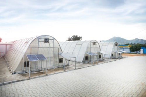
Drying is the process of removing excess moisture from a given organic/nonorganic product and preserving those products for a longer duration of time. Earlier the drying process was employed at large for drying the agricultural items, now it has been extended to several industrial
products/non-industrial products. Population explosion and requirements of the general public has caused a severe demand on the items. To meet the enhanced demand on the products can be effectively achieved by going in for the drying process. Drying is an energy-intensive process. Hence, to economise the consumption of conventional thermal energy, solar thermal energy is being harnessed to dry the given product or the given batch of product.
Key words
Drying, moisture, organic/non-organic matter, industrial product/non-industrial product, preservation, conventional thermal energy, solar thermal energy, product or batch of product.
Introduction
The industrial and the non-industrial products are the primary requirements for all living beings. Due to the increase in the population, the production of food, as well as industrial products, does not tally with the increased demand. To achieve the balance between the population and the production can be done either by limiting the population or by enhancing the production or reducing the losses in these products at each and every stage. The third option is achieved effectively by selecting the solar drying method. The solar drying method is an economical and effective method; wherein solar thermal energy (STE) is harnessed to remove the moisture from the given product.
Research and development in the field of solar energy application have resulted in the availability of various types of solar drying devices. One of them is the indirect passive solar drier (IPSD). Driers from low cost, low technology to reasonable cost/high cost, high technology are available in the market. In the present article, an attempt is made to operate two IPSD to achieve continuous production of the dried product.
Theory
Drying is the process of removing the prescribed amount of moisture/water from the given product. It is noted that the microorganisms that cause spoilage and decay grow and multiply in the presence of water. Also, many chemical changes in the given product and other biological material can function only in the presence of water. When the water moisture is reduced below 10 percent wet bulb temperature (WB), the microorganisms and other things cease to function. The values of drying temperature and the retaining of a safe level of moisture content are different for different types of industrial and non-industrial products. During drying, heat energy is transferred from the surrounding medium to the surface of the product and a fraction of the heat energy penetrates into the product, resulting in heating the product and evaporating the water moisture present within the product as well as from the surface of the product.
Drying involves both heat and mass transfer processes simultaneously. In convective drying, the heat energy required for removing moisture is supplied by the hot air. Industrial and non-industrial products may have different types of moisture. This moisture level value depends upon the relative humidity of the air. There are four types of drying methods and the drying process is complex and non-linear. It depends on a large number of physical, chemical, and psychometric parameters. There are eight important moist air thermodynamic parameters, which are to be taken into consideration. The most important parameter is the saturation pressure, which depends on the temperature. Usually, a psychometric chart is used in calculating these parameters.
Drying industrial/other products directly under the sun is a common practice. However, this method has several drawbacks, like the possibility of contamination of the product, decaying/spoilage of the product, and consumption of the product by birds and insects. Considering these factors, solar dryers have been developed to produce good quality dried products.
Solar drying and driers
Average solar radiation energy received on the horizontal surface in India is in the range of 1674.8 J/ cm2/day – 29109J /cm2/day. Solar intensity varies with seasons of the year within the range of 1256.1J/ cm2/day – 29109J/ cm2/ day. The solar intensity on the optimally inclined surface will be higher than these values. The solar heat energy is transferred to the surface of the product by conduction from the heated surface that is in contact with the product by conduction and convection from the sun.
The products will absorb the heat energy and the moisture contained within them will be vapourised. As the heat gets absorbed by the product, the hot air circulating around them gets cooled and its humidity increases. Since the air has a low heat capacity rate as compared to the high latent heat of vapourisation of water moisture, a large volume of air with appreciably low humidity is necessary in the case of solar drying.
There are different methods of solar drying
*According to the mode of heat transfer
*Open sun drying
*Direct solar drying
* Indirect solar drying
The solar dryers can be classified as…
*Open sun drying and
*Controlled solar drying.
The controlled solar drying is further classified as…
*Passive solar dryer and
* Active solar dryer
Again further classifications in both the above-said classifications are direct solar dryer and indirect solar dryer and mixed-mode solar dryer. In all these classifications various types of solar dryers have been developed. I PSD is selected for the present innovative design concept.
The design criteria of the solar air heater to be used for the drying purpose depends on the drying requirements of the different industrial/non-industrial products; this is the most important among all, which includes the temperature and airflow rate for particular climatic factors; here the ambient air temperature, the ambient relative humidity, the solar intensity, and the wind velocity during the time of operation are to be considered. It is always better to design the solar air heater for the worst conditions possible (size, shape, and dimension requirements).
Material of construction; it is the process of selecting appropriate material available in the market for construction of the solar air heating device/absorber, selective surface coating, glazing materials, insulating materials, and other required suitable materials. The solar drying chambers (SDC) of IPSDs consist of perforated trays on which the given products are kept, a door is provided on the north side of the SDC to load or unload each tray, a baffle, a chimney at its top, and the fluidics diode.
Fluidics
The National Fluid Power Association has defined fluidics as one in which sensing, controlling, information processing, and logic operation are performed primarily through fluid dynamics, without the use of any type of moving parts. Fluidic systems are similar to electronic systems in many ways. Almost all the counterparts of the electronic systems are found in fluidics systems. In the fluidics amplifiers, the flow of a high-energy fluid jet/power jet is controlled by a low-energy fluid jet/control jet and exit out of the outputs. The fluidics devices are like logic gates. Diodes, sensors, and other fluidics devices are also available, which are used for different applications. Most of the fluidics devices are similar to the fluidics amplifiers and both have the same features. There are mainly five types of fluidics amplifiers along with different types of fluidics devices and their classification is based upon the principle of operation. Bistable Fluidics Amplifier (BFA) is one of the fluidics amplifiers used in a number of applications and is a wall attachment (Coanda`s effect) type amplifier.
Generally, a fluidics amplifier consists of a power jet chamber with a power nozzle to produce P. Subsequent to the power nozzle, two control chambers with respective control nozzles and control ports C1 and C2 are machined. In between these control nozzles, a well-designed jet interaction chamber is located. Two output conduits with output ports O1 and O2 are located below the jet interaction chamber. These output ports are separated by an appropriate splitter/divider. The dimensions and design of the device itself depend upon the power, capacity, pressure time, frequency, gain, efficiency, and characteristics required of the device. Initially, P will be made to get attached to either of the boundary/attachment walls of the output conduits providing stable output in one of the output ports, till a proper control signal input is supplied at the appropriate control port. In the present paper, this amplifier is employed as a diverter valve (DV) for automatically diverting the hot air stream, from SSAH to the respective inlets of the two IPSDs.
The fluidic devices are used for logic operations, information processing, control operations, sensing operations, and other operation. Different types of fluidics devices are available; including fluidics diodes. Out of different types of fluidics diodes, fluidics vortex diode (FVD) / simple solar air heater (SSAH) Fig 1 is an important fluidics device and is used in a number of applications. FVD consists of a vortex chamber/cylindrical chamber with the tangential inlet fitted with a power nozzle to produce a power jet within the chamber. The outlet port is at the center of the upper circular surface of the chamber and is welded to the surface to minimise the shading effect. Surrounding air is issued tangentially in the form of a jet, and it swirls within the chamber before it flows out. This results in a longer flow path for the air stream and facilitates enhanced heat transfer. Advantages of FVD are: simple and economic, no moving parts hence, no wear and tear, characteristic and performance are not affected, FVD has smaller collector surface area, but has the enhanced capacity of the rate of heat absorption, and to get the same capacity with any other devices, the collector surface area would be three times larger than the surface area of the fluidic device, there is no shadowing effect.
Methodology
IPSD is integrated with BFA and FVD is as shown in figure 02. IPSDs, BFA, and FVD are designed and built as per the requirements and are placed above the ground level on the respective stands. All these devices are connected by leak-proof flexible connectors. FVD has to be placed lower than BFA to utilise up draught characteristics of hot air. Whereas IPSDs are placed either at the same level of BFA or a little bit elevated level than the position of BFA. FVD outlet pipe is connected to the power chamber of BFA. One of the output ports O1 of BFA is connected to the inlet of the first IPSD-1 and the other one O2 is connected to the inlet of the second IPSD -2. The control ports C1 and C2 are connected to the bent tubes/flow sensors, which are placed inside SDC with their tips in the vicinity of the bottom surfaces of the topmost trays. As and when the trays are loaded in any one of the IPSD, they bend down and block the tips of one of the flow sensors respectively. Now when the product kept in IPSDs is dried to the required value, the trays get straighten, the flow sensor tips are opened, and sense the flow rate of the hot air stream. BFA is designed to constrain P initially to be continuously attached to the boundary wall on O1 port side. P switches to the output ports O1or O2 depending upon the sequence of the control signal is transmitted from the flow sensor tips to the control ports C1 or C2. A very important point to be noted that all the three – FVD, IPSD and BFA should thoroughly insulated except for the collector surface (upper circular surface) of FVD with appropriate insulation material to prevent heat loss from the integrated drying system to the ambient air.
The hot air stream is generated by FVD. FVD chamber is always filled with the surrounding air. When FVD is kept under direct solar energy, FVD’s collector absorbs the heat energy and is transferred to the air within the chamber facilitating producing the hot air. Due to the convective buoyancy, a partial amount of hot air flows out of the outlet and creates a partial vacuum within the chamber. The partial vacuum of even a small amount within the chamber will facilitate the surrounding ambient air to rush into the chamber. Thus there will be a continuous supply of hot air to IPSDs, via BFA.
Working of IPSDs Integrated with BFA
The trays of IPSD 1 are loaded with the product/the batch of product to be dried and due to the weight of the product, each tray bends a little bit blocking the tips of the flow sensors. The hot air stream from SSAH enters the BFA`s power chamber and is issued as P in the interaction chamber.
As per design P initially gets attached to the wall on the O1 side and flows below the trays of IPSD 1. The absorption of heat by the product facilitates the evaporation of moisture and results in the loss of weight and shrinkage of the product. The reduction in the weight of the product promotes the straightening of each tray. The hot air flowing over and around the product heats the product, enhances the rate of drying, and increases the rate of weight loss. The loss of weight results in the straitening of the trays, which in its turn opens up the flow sensor`s tip located at the bottom surface of the topmost tray in the first IPSD 1. The increased air mass flow rate into the sensor`s tip generates the required input at C1 to switch the hot air stream to be diverted to the second IPSD 2 via O2. Due to the similar drying process in IPSD 2, a required control signal is generated at C2 to facilitate switching the hot air stream from IPSD 2 to IPSD 1. Thus hot air goes on flowing continuously through either of the IPSDs till enough is required. It should be noted that the hot airstream gets diverted only when the required strength of the control signal is available at one of the respective control ports. This signal strength is due to the increased amount of air mass flow rate through the flow sensor`s tip.
This is possible when the product`s total weight loss during the drying process can be standardised by calibrating as per requirement. When the hot airstream is switched from IPSD 1 to IPSD 2, the dry product is removed from IPSD 1 chamber and a fresh product is loaded. Similarly, when the hot airstream switches again to IPSD 1 from IPSD 2, the dried product is taken out of IPSD 2 chamber and is loaded with fresh product. Thus a continuous production of the required dried product can be achieved.
Maintenance
The present design concept has four different devices integrated to get continuous drying of the given product. FDV has to be cleaned especially the glazing at least once in two days. The leakages and the inclination should be checked often and repaired. Insulation should be checked to avoid heat losses to the surrounding atmosphere. BFA`s conduits should be kept clean to avoid obstruction for hot airstream through it. BFA`s should be located in such a way that there is no backflow from the IPSDs. Insulation around BFA should also be checked frequently. IPSDs trays and most of the parts should be cleaned as per the requirement. The flow of moisture air may corrode of IPSDs chamber, trays, chimney, and chimney cover. The insulation provided to IPSDs and leakage should be checked and repaired. The framework of the stands should be checked for corrosion and should be repainted once a year.
Conclusion
The present article is an innovative system developed for the continuous drying of a given product by incorporating a simple fluidics amplifier BFA and a fluidics device in the conventional solar drying process. Though solar driers are more expensive and less efficient as compared to other types of conventional driers, the advantage is that solar driers positively conserve the conventional energy sources. Also incorporating Bistable Fluidics Amplifier (BFA) ensures the effective working of the system to achieve the pre-set objectives. The improvement in drying in the overall/total production enhancement on average is expected to increase by 12 percent. This innovative method can be used to dry any industrial/ non-industrial product economically. No moving parts are involved in the present system. Any type of material can be used to fabricate BFA, whereas FVD and IPSDs are to be constructed with standardised material to achieve optimum performance. The said system is a maintenance-free, economical, and efficient device. Integration of BFA with FVD and IPSDs might increase the system cost by no more than 0.6-0.8 percent of the original total cost of IPSDs. Experimental investigations will ensure the anticipated performance of this novel design concept.


