Abstract
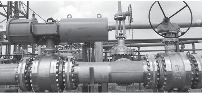
In an industrial plant, it is important to restrict noise. It can cause irritation and prolonged exposure to higher decibles can be fatal. OSHA standard defines and regulates noise in equipment’s. Also each instrument has its own noise limitation. However, after all these limitations in a plant the average noise exceeds the limit human ear can bear. Control valve noise is a big concern for plant operators and can cause the plant to stop and reduce profitability. Noise cannot be nullified in a valve but can be reduced to a great extent that plant operators can bear. Use of steam is common in these power, refinery or fertilizer industries and other processes. If there is more process drop in a process, one needs to pay more attention on noise attenuation. In control valve when noise attenuation technique is carried out we need to ensure the process controllability of valve is also not disturbed. By reducing the noise the plant efficiency and life span of valve can also be increased. This paper determines the different methods that can be used to limit the control valve noise for ensuring the safety for plant and its workers. Noise can be treated by source treatment or path treatment. Source treatment is method of reducing the generation of noise and path treatment is method of reducing the noise after generation from valve trim to outlet of the pipe.
Introduction
As defined by OSHA, noise level for control Valves is to be limited to 85 dBA for gaseous service which is aerodynamic noise. For liquid service there is no such limitation since sonic velocity of gas is very high when compared to liquid.
ISA 75.17 defines aerodynamic noise generated in valve. As a method to predict the noise generated in a control valve of standard design by the flow of compressible fluid and the resulting noise outside of the pipe i.e. downstream of the valve. The transmission loss (TL) equations are based on a rigorous analysis of the interaction between the sound waves that exist in the pipe and many coincidence frequencies in the pipe wall. The pipe wall thickness reduces the noise by increasing the thickness. The equations in this standard make use of the valve sizing factors defined in ANSI/ISA-S75.01 and ANSI/ISA-S75.02. This method was developed from the fundamental principles of acoustics, fluid mechanics, and mechanics. IEC 60534-8-4:2015 establishes a method to predict the noise generated in valve by liquid flow and the resulting noise level measured downstream of the valve. The noise may be generated both by normal turbulence and by liquid cavitation in the valve. Pressure is an important parameter for noise calculation, the pressure in the vena contracta is developed from the definition of FL which is referred in ANSI/ISA-S75.01.
A control valve controls flow by converting pressure energy into kinetic energy. Some of this energy is transferred to the pipe wall as vibration, and a portion of this is radiated as noise. Most of the energy is converted to heat through viscous friction. At the vena contracta there is a pressure that may be even lower than the downstream pressure. The different regimes of noise generation are the result of differing sonic phenomena or reactions between the molecules in the gas and the sonic shock cells. In Regime I, flow is subsonic and the gas pressure is partially recovered or recompressed. In Regime II, sonic flow exists, with interaction between shock cells and with turbulent choked flow mixing. Pressure recovery is less as the limit of Regime II is approached. In Regime III no isentropic pressure recovery takes place. In Regime IV the shock cell structure diminishes as a “Mach disk” is formed. In Regime V there is a constant acoustic efficiency. ISA 75.07 defines equipment, methods, and procedures for the laboratory testing and measurement of airborne sound radiated by a compressible fluid flowing through a control valve and its associated piping, including fixed-flow restrictions.
Detailed Analysis
Source treatment is killing the noise in its origin which is generally valve trim and distributing pressure drop in valve port area by using low noise trims. Noise reduction trim are used for reducing the noise production in valves. In gaseous service there are specialized cages with mini holes which distribute the pressure loss in an evenly manner, the number and distance between holes are determined with respect to the amount of pressure loss to be distributed. Noise calculation in valve is made at valve outlet and also at 3m from valve outlet. For liquid service since the sonic velocity is less when compared to gas service, the limitation for liquid service is approximately 100 dBA and for the same anti cavitation cage is used for limiting the noise with same distribution of pressure loss principle. In liquid service mainly cavitation causes noise which is bursting of bubbles caused with respect to vapor pressure relation. Other effects like flashing and choking are very minimal contributors for noise. Valve characteristics recommended for control valve are either linear or equal percentage and when it is low noise trim then characteristics would be modified linear or modified equal percentage. We need to ensure that the controllability of the process is not disturbed.
For service where specialized cages cannot limit the noise, we can use path treatment which is reduction of noise after generation and in outlet of valve. In that case, diffuser is used which is distribution of pressure loss with enlarged space above the line size for reducing both noise and velocity.
For vent service in which process is vented out to atmosphere, pressure loss is enormous and in such cases silencer is used which is similar to a diffuser. However, even after use of silencer, noise generated during vent out will be approximately close to 110 dBA it is acceptable since venting does not happen often. In service where heat dissipation is not allowed in order to maintain process fluid nature as it is, insulation of line along with valves are offered. Insulation is also used if above discussed noise limitation parameters are not effective so that every meter of insulation thickness reduces approximately 3 dBA of noise. If pressure loss i.e. difference between inlet and outlet is enormous, the pressure loss can be split into two or three valves so that noise generation can be reduced. However, this option increases the cost of procurement since quantity of valve is increased. As process flow cause noise with pressure difference all the instruments that causes noise generation should have noise limiting ability like control valve does. Apart from instrumentation other mechanical items like pumps and flow equipments should have options to limit noise generation. Velocity is also very important, as it is related to noise and for gas which Mach is greater than 0.33 would have noise greater than 85dBA. Pipe schedule increase is another step for reduction in noise, as thickness of pipe wall would also reduce the amount of noise exposed out of pipe line.
Reduction of noise in a valve is not effective if multiple valves are placed together the average noise will be high due to cumulative effect of noise. For rotating equipments for which noise generated is very high they will be normally placed inside a room, however for plant operators who needs to work near those instruments will be using PPE and same would reduce the noise to a limited extent and not fully. Similarly, valves for anti-surge application, pressure reducing desuperheater can be placed with wall covered for noise prevention. For the same, plants are located in remote location away from residential area. Also with respect to growing population circumference of residential area is extended keeping the industrial area in mind. Plant operators who are exposed to noise for prolonged period are more prone to the hazards. This has to be minimized by conducting medical awareness program to workers. Instruments location is very important and more noise generating instruments should be located separately. So that, cumulative noise generation can be avoided. Every plant should have insulation by default to limit the noise, irrespective of requirement of heat dissipation.
Conclusion
Noise generation in a valve cannot be nullified.However, it can be reduced by above described methods and in future more advanced methods of noise reduction would be introduced. For controlling the process as desired we need to choose to reduce noise to avoid process disturbance and also to provide safety to plant operators. In design stage, if we focus more on reducing noise perspective like process reducing; dropping pressure step by step, civil functions providing additional supports for reducing vibrations and reducing sudden change in pipe orientation by using curved pipe design and control system opting for optimum source or path treatment for noise application in control valve is more efficient and productive. Noise limitation should be followed strictly throughout the plant with norms same seriousness as that of carbon emission, waste treatment plant that are controlled by pollution control board as noise is also pollution.
Standards:
1. OSHA -1910.95- Occupational noise exposure
2. ISA 75.17- Control Valve aerodynamic noise prediction
3. IEC 60534-8-4:2015 Industrial process control valves
4. ISA 75.01 Control Valve sizing
5. ISA 75.07 Laboratory measurement of noise


