Separating entrained liquids from gas / vapours is a very important function in many chemical processes e.g. stripping entrained water particles from steam exiting a boiler drum, entrained water particles from gases entering a compressor and stripping oil even to < 5 PPM from flooded screw compressors delivered gases . Read on to get full details on Stripping Liquids from Gas / Vapours.
Why strip liquids from gases and vapours?
Boiler drums exiting saturated steam entrained water particles reaching the super-heater could damage it. < 5 ppm oil content in flooded screw compressors delivered gases is necessary for downstream processes using the gas and to recover the oil for reuse for saving oil costs. > 5 ppm oil content in the instrument damages the valve positioners and other precision pneumatic instrument components. Thus, the reason for efficiently and effectively stripping liquids from gases is an indispensable operation in many chemical processes. Separators using demister pads play a very important role in Stripping Liquids from Gas / Vapours.
Demister Pads
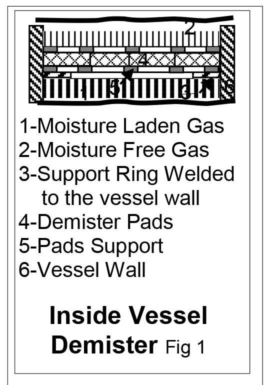 Demisters pads debuted in the late fifties. Special wrinkle wire woven mesh layers pads constitute demister pads. Designers select pad length, width, and thickness (fig 1, item 4) to suit vessel sizes and application requirements. The pads supported on suitable frame (item 3) constitute the demister pad assembly. Wires tie the demister assembly (DPA) to the support ring. However, bolting the DPA to the support ring is preferable. DPAs besides stripping the liquids from gases and vapours effectively, offer very low flow resistance i.e. low pressure drops, another plus point, which no other separating device offers. Hence, demister pads’ wide application in almost all liquid stripping tasks in chemical, petroleum, pharmaceutical, light industry, metals producing plants, seawater desalination and desulfurization processes to remove oil mist from gases including toxic and poisonous.
How Demisters Strip liquids from gas / vapours? Working principle of demister pad
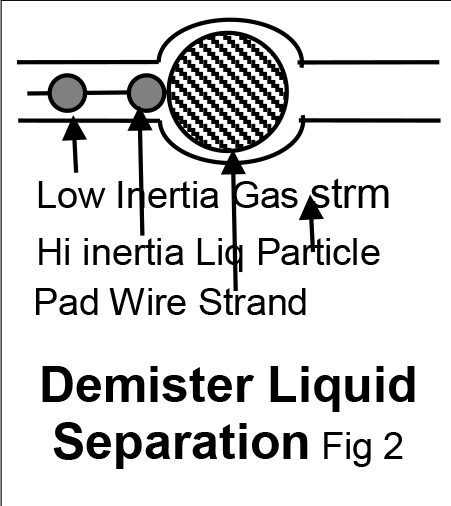 The low inertia travelling gas stream bends around the demister wire strand (fig 2) and moves on; but the entrained high inertia liquid particles travel straight, collide with the demister pad wire and adheres to it. The adhering mist particles diffuse on the filament surface, travel along the filament wires till it reaches a two wire intersection and stop there. Moreover, thus separated liquid particles reach there and join with the first stopped driplent. They combine with one another and grow bigger and bigger. This phenomenon is called coalescence. When the particle has grown sufficiently big and its weight exceeds the gas stream velocity imparted and liquid adhering surface tension forces, it drops to the vessel bottom and collects. Draining the collected liquid periodically, maintaining prescribed liquid level collects the liquid e.g. oil flooding a screw compressor for reuse. The liquid freed gas / vapour exits the demister pads for use in subsequent processes.
Separating liquids from gases / vapours improves exiting gas quality fit for uses, optimizes the process, reduces gas / liquid using equipment corrosion, extends their lives, decreases air pollution and recovers the liquids for reuse where applicable.
Demister Pad Features
Below given are demister pad features:
a. Simple structure
b. Lightweight and easy to transport
c. High porosity, less pressure drops.
d. Large surface area and high separating effi ciency.
e. Easy to install, operate and maintain
f. Durable and long service life
g. Corrosion and rust resistance
h. Long live
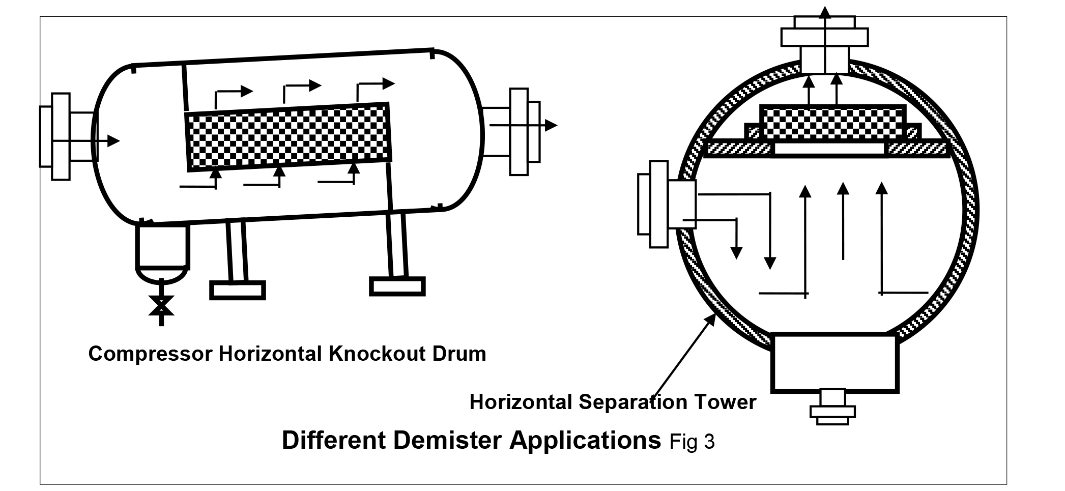 Demister pads come in four models: 1 standard type, 2 efficient type, 3 high penetration type and 4 shock absorber type. Table 1 lists a standard type demister pad specifications and fig 2 shows two demister pad applications.

Demister Pad Salient Details
Demister pad separation efficiency depends on the voids and the specific wire mesh surface area. It increases with gas flow velocities, up to the manufacturer recommended velocities. At still higher velocities, the separated liquid floods the pads, the gas re-entrains the liquid and separation efficiency materially decreases. Most pads’ separation efficiency is 99.9% for droplets diameters. The maximum droplet diameter for 5 to 12 µm droplets diameters. On request, vendors offer separators containing specially designed pads to separate droplets as low as 3 µm. As table 1 shows, 0.1 mm and 0.5 mm pad mesh wire dia, 150 to 1100 m2/m3 specific surface areas are common. The manufacturers provide specially designed supports and/or cover grids to support the mesh pads. Additionally, they arrange the grids to get approximately 90% free flow areas. Field crew installing the demisters shall ensure the pads tight fit with the vessel wall and with one another to avoid the moisture laden gas bypassing demister pads assembly.
The pad of the wire mesh droplet separators (demisters) is between 100 and 150 mm deep in most applications. If the gas- or steam flow contains very fine droplets, e.g. as created during condensation, considerably deeper pads or multiple layers are required
Demister Pad Maintenance
After using for a long time, the demister pad will clog or develop flooding problem and consequently lead to increased pressure drops, because of gas carried over particles fouling and reducing gas pass paths area. Periodic demister maintenance prevents this problem. Water or other harmless solvent wash and sun drying mostly restore the demisters’ performance.
Demister Case Study 1:
Fouled demister pads, consequent too poor granulator performance a month after commissioning threatened total ammonia and urea complex shutdown
A large fan delivers air at around 2000 mm WC to strip moisture out of the stationary granulator granulated urea. The foreign process licensor engineer asked the author to lower the Demister Pads (D) containing Duct Spool (DS fig 4) flanged to the 10 m elevation 2000×1500 mm rectangular air duct and to bolt the DS back to the duct after he water washes the demisters
Constraints
The author faced the following constraints:
Suddenly decided heavy task & too short permitted completion time
Scaffolding, unbolting the over 250 Nos. of 10 mm dia DS flange bolts, and DS lowering from 10-metre elevation and assembling back are min 24 hours tasks
The long boom crane to lower the DS is available for hire fifteen days hence only
The permitted time for the hardest and impossible to overcome constraint task was 6 hours only because of the below given constraints:
Bi-urate content – an impurity in surge tank stored partially processed urea solution – increases to unacceptable 1%
The above can’t be re-processed
Nor can it be dumped because of strict pollution regulations
Longer than 6-hours granulation section SD requires shutting down the high pressure synthesis section also
Correcting the several 250-bars large size flange leaks usually seen during Synthesis Section restart might extend the shutdown indefinitely
The missed urea and NH3 export orders deliveries heavy penalties aggravated the situation still more
Hence, the task should be completed in 6 hours by hook or crook
The author’s first innovative idea of in-situ demister cleaning saved the day:
Pre-shut down tasks: 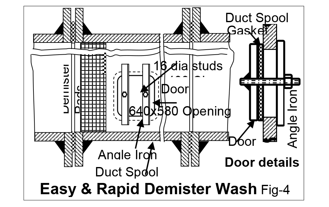 Field crew installed the scaffolding, water hose connection and flame cutting set at DS
They chalk marked 600×540 mm opening at DS bottom
The shop made a 640 high x 580 wide x 10-mm thick door
They cut 660×600 mm door gasket out of 4.5 mm thick scrap conveyor belt piece
The author put a hold – drill the several 12 mm dia bolt holes for bolting the door to the duct after he Okays it.
Fortunately, the second innovative idea that flashed during the tasks progress:
The shop welded two Nos. of 16 dia x 50 mm long studs 400 mm apart (see fig 4- door details).
Inserted the gasket over the studs via holes cut in the gasket. The door + gasket was ready in 2½ hours!
Operators shutdown the granulation section an hour after pre-shutdown task-start and issued hot work permit to flame cut the person-entry opening on the DS an hour later. Further tasks proceeded thus:
Field crew flame cut the marked opening (O; Fig 4)
Operators entered the DS via O and water hosed the demisters in-situ. The dirty water drained to the waste water disposal system via the existing 2” drain pipe
The operators exited the DS
They inserted the door via the opening diagonal, matched the door with the opening, inserted the angle irons on the studs and tightened the nuts – just a 15 minutes task. In addition to bolting load the air pressure too loads the door making it leak tight akin to a boiler drum man-hole and hand holes doors.
Granulator was ready for use in 5 hours – a much feared total shutdown averted most economically and with least efforts!
Advantages of the two innovations are:
The much feared and terrible financial loss causing 24 or more hours synthesis section outage gone
Immediate job completion and continued full capacity plant operation was possible because of not using, the 15-days later available crane
Thanks to the two innovative ideas jobs were complete easily, economical
Above all, it averted granulator shutdowns for demister cleaning – recurring in two weeks task – as under:
Operators themselves clean the demisters within an hour during periodic ½ shift long granulator cleaning shutdowns without maintenance help.
They use the maintenance provided permanent cat ladder, cleaning water connection and working platform at DS.
Case Study 2:
4500 T yearly lost ammonia production and the upstream plants produced & wastefully vented RFG to produce it:
Problem details; Yearly 4500 Tons lost ammonia production from Syn Gas Compressor K 601 Intermediate Pressure Barrel (IPB) low throughput shutdown the ammonia plant 5 days ea. six monthly.
Crew found highly eroded last 2 labys 6 months after commissioning shutdown. None did RCA; they lived with the 6-monthly ammonia plant shutdown, lost production and other losses over 9 years.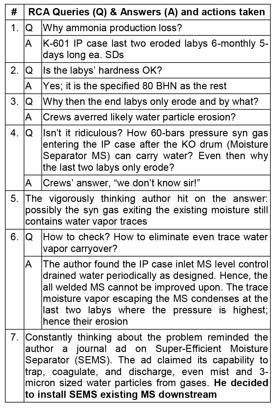
Author’s RCA: The table given above is a set of Q&A during RCA after the author taking over as maintenance superintendent. He did the root cause analysis that solved the problem forever:
RCA Benefits: SEMS arrived 6-months later. Crew installed it existing MS downstream. Vanished 6 monthly SDs surprised one and all. However, how the SEMS performs so well is still a mystery as the vendor declined supplying the all welded SEMS section drawing under the pretext of “proprietary confidential information, and the SEMS requires no field maintenance!”


